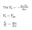
Q. A voltage amplifier is constructed using enhancement mode MOSFETs labeled M1, M2, M3 and M4 in the figure below. M1, M2 and M4 are n-channel MOSFETs and M3 is a p-channel MOSFET. All MOSFETs operate in saturation mode and channel length modulation can be ignored. The low frequency, small signal input and output voltages are 𝑣𝑖𝑛 and 𝑣𝑜𝑢𝑡respectively and the dc power supply voltage is VDD . All n-channel MOSFETs have identical transconductance 𝑔𝑚𝑛 while the p-channel MOSFET has transconductance 𝑔𝑚𝑝. The expressions for the low frequency small signal voltage gain 𝑣𝑜𝑢𝑡/𝑣𝑖𝑛 is
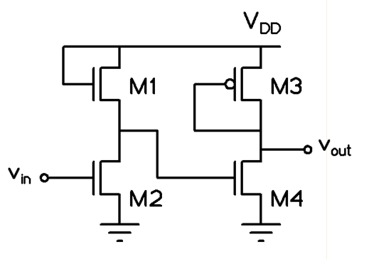
Ans: +gmn/gmp
Sol:
M1, M2, M3, M4 are in saturation mode
M1, M2, M4 → NMOS
M3 → PMOS
By using small signal analysis
We can replace M1 and M3 by the internal impedance because drain and source terminal are short circuited
Now replace MOSFET to small signal model