Alternating current (AC) is an electric current which periodically reverses direction and changes its magnitude continuously with time in contrast to direct current (DC) which flows only in one direction.
Ac Voltage applied to a Resistor
Resistance is the opposition to the flow of the current offered by any substance. The substance that limits the flow of electric current in the circuit is the resistor. If the source is producing current that varies with time periodically, then this current is called alternating current. Here, we are considering that the source is producing sinusoidal varying potential difference or voltage across its terminals. We can represent it as
V=VmsinωtV=Vmsinωt
Where VmVm represents the amplitude of the oscillating potential difference and represents the angular frequency. In the below article, we will describe what will happen when we apply the AC voltage source to a resistor.
Representation of AC Current and Voltage by Rotating Vectors — Phasors
The analysis of an ac circuit is by using a phasor diagram. A phasor is a vector which rotates the origin with angular speed ω, as shown in the fig given below.
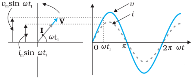
The vertical components of phasors i and v represent the sinusoidally varying quantities v and i. The magnitudes of phasors I and V represent the amplitudes or the peak values im and vm of these oscillating quantities.
The projection of voltage and current phasors on vertical axis,
i.e., im sinωt and vm sinωt respectively represent the value of current and voltage at that instant.
AC Voltage Applied to an Inductor
An inductor can oppose or block the passage of alternating current through it. There are two cases to do so. One case is for the DC circuit, and another is for the AC circuit. The first inductor is connected to a DC supply, and the second one is connected to the AC supply.
In the DC circuit, a constant current flows through this inductor, and the bulb connected to it glows brightly. But in the AC circuit, the bulb does not lighten up as brightly as the first one; this happens because the inductor opposes the flow of alternating current.
AC Voltage applied to a Capacitor
When a capacitor is connected to a voltage source in a dc circuit, current will flow for the short time required to charge the capacitor. As charge accumulates on the capacitor plates, the voltage across them increases, opposing the current. That is a capacitor in a dc circuit will limit or oppose the current as it charges. When the capacitor is fully charged, the current in the circuit falls to zero.
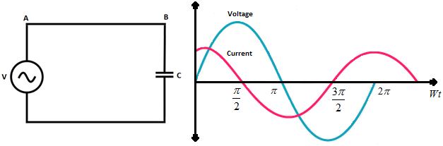
When the capacitor is connected to an AC source, it limits or regulates the current, but does not completely prevent the flow of charge. The capacitor is alternately charged and discharged as the current reverse each half cycle.
AC Voltage Applied to a Series LCR Circuit
Consider the circuit shown above. Here, we have an inductor, a resistor, and a capacitor connected through a series connection across an AC voltage source given by V. Here, the voltage is sinusoidal in nature and is given by the equation,
![]()
Here, vm is the amplitude of the voltage and ω is the frequency.
If q is the charge on the capacitor and i the current at time t, we have, from Kirchhoff’s loop rule:
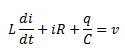
Here, q is the charge held by the capacitor, I is the current passing through the circuit, R is the resistance of the resistor and C is the capacitance of the capacitor. In order to determine the instantaneous current or the phase of the relationship, we will follow the analytical analysis of the circuit.
Power in AC Circuit: The Power Factor
Power factor, cos(Φ), is an important part of an AC circuit that can also be expressed in terms of circuit impedance or circuit power. Power factor is defined as the ratio of real power (P) to apparent power (S), and is generally expressed as either a decimal value, for example 0.95, or as a percentage: 95%.
Power factor defines the phase angle between the current and voltage waveforms, were I and V are the magnitudes of rms values of the current and voltage. Note that it does not matter whether the phase angle is the difference of the current with respect to the voltage, or the voltage with respect to the current.
LC Oscillations
The electric current and the charge on the capacitor in the circuit undergo electrical LC oscillations when a charged capacitor is connected to an inductor. The electrical energy stored in the capacitor is its initial charge which is named as qm. It is represented by
![]()
The inductor contains zero energy. Charge varies sinusoidally with respect to time.
LC oscillations is not realistic for two reasons:
(i) Every inductor has some resistance. The effect of this resistance is to introduce a damping effect on the charge and current in the circuit and the oscillations finally die away.
(ii) Even if the resistance were zero, the total energy of the system would not remain constant.
Transformers
A transformer is a device that can change the potential difference or voltage of an alternating current: a step-up transformer increases the voltage. a step-down transformer reduces the voltage.
A transformer consists of two sets of coils, insulated from each other. They are wound on a soft-iron core, either one on top of the other or on separate limbs of the core. One of the coils called the primary coil has Np turns. The other coil is called the secondary coil; it has Ns turns. Often the primary coil is the input coil and the secondary coil is the output coil of the transformer.
The equations obtained above apply to ideal transformers (without any energy losses). But in actual transformers, small energy losses do occur due to the following reasons:
(i) Flux Leakage: There is always some flux leakage; that is, not all of the flux due to primary passes through the secondary due to poor design of the core or the air gaps in the core. It can be reduced by winding the primary and secondary coils one over the other.
(ii) Resistance of the windings: The wire used for the windings has some resistance and so, energy is lost due to heat produced in the wire (I 2R). In high current, low voltage windings, these are minimised by using thick wire.
(iii) Eddy currents: The alternating magnetic flux induces eddy currents in the iron core and causes heating. The effect is reduced by using a laminated core.
(iv) Hysteresis: The magnetisation of the core is repeatedly reversed by the alternating magnetic field. The resulting expenditure of energy in the core appears as heat and is kept to a minimum by using a magnetic material which has a low hysteresis loss.