Electric Current
An electric current is a flow of electric charge in a circuit. More specifically, the electric current is the rate of charge flow past a given point in an electric circuit. The charge can be negatively charged electrons or positive charge carriers including protons, positive ions or holes.
Currents are not always steady and hence more generally, we define the current as follows. Let ∆Q be the net charge flowing across a cross section of a conductor during the time interval ∆t [i.e., between times t and (t + ∆t)]. Then, the current at time t across the cross-section of the conductor is defined as the value of the ratio of ∆Q to ∆t in the limit of ∆t tending to zero,
In SI units, the unit of current is ampere.
Electric Currents in Conductors
Electrical conductors are the material that allows the free flow of electrons through them. This means they allow electrical current to pass through them. Electrical conductors are generally made up of copper, aluminum, and their alloys.
The electrical charges in an electric conductor move from atom to atom as the potential difference is applied through them. Mostly the electric conductor is used in the form of wire. The electrical conductor used to transfer electricity is normally stranded.
Compared to a single wire of the same cross-section area, stranded conductors have great flexibility and mechanical power. In this article, you will learn what makes an electric current flow in a wire.
Ohm’s Law
A basic law regarding flow of currents was discovered by G.S. Ohm in 1828, long before the physical mechanism responsible for flow of currents was discovered. Imagine a conductor through which a current I is flowing and let V be the potential difference between the ends of the conductor. Then Ohm’s law states that
V ∝ I
or, V = R I
where the constant of proportionality R is called the resistance of the conductor. The SI units of resistance is ohm, and is denoted by the symbol Ω. The resistance R not only depends on the material of the conductor but also on the dimensions of the conductor. The dependence of R on the dimensions of the conductor can easily be determined as follows.
Drift of Electrons and the Origin of Resistivity
Under normal circumstances the free electrons move randomly from one atom to another. The velocity with which this random motion is taking place is called Thermal Velocity. The average thermal velocity is said to be zero as the entire motion on an average is random. This is the condition where no electric field is applied.
When an external electric field is applied on the conductor, the electrons or the negative charges are attracted towards the positive charge. When the electrons rush out from the atom, the atom then becomes a positive ion. Thus, these positive ions are attracted towards the negative charge. But as the mass of the positive ion is very high comparing with the electrons, the positive ions do not move. The electrons are accelerated towards the positive charge. A number of collisions also occur with those positive ions and thus these electrons possess a velocity. The average of this velocity is called the drift velocity. With the drift velocity, the flow of electrons is drifted towards the positive end.
Mobility
Conductivity arises from mobile charge carriers. In metals, these mobile charge carriers are electrons; in an ionised gas, they are electrons and positive charged ions; in an electrolyte, these can be both positive and negative ions.
An important quantity is the mobility μ defined as the magnitude of the drift velocity per unit electric field:
Limitations of Ohm’s Law
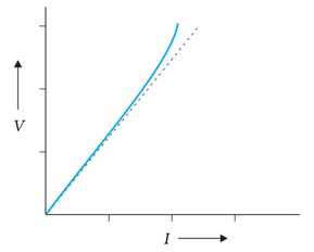
Although Ohm’s law has been found valid over a large class of materials, there do exist materials and devices used in electric circuits where the proportionality of V and I does not hold. The deviations broadly are one or more of the following types:
(a) V ceases to be proportional to I.
(b) The relation between V and I depends on the sign of V. In other words, if I is the current for a certain V, then reversing the direction of V keeping its magnitude fixed, does not produce a current of the same magnitude as I in the opposite direction.
(c) The relation between V and I is not unique, i.e., there is more than one value of V for the same current I. A material exhibiting such behaviour is GaAs.
Resistivity of Various Materials
The materials are classified as conductors, semiconductors and insulators depending on their resistivities, in an increasing order of their values. Metals have low resistivities in the range of 10–8 Ωm to 10–6 Ωm.
Commercially produced resistors for domestic use or in laboratories are of two major types: wire bound resistors and carbon resistors. Wire bound resistors are made by winding the wires of an alloy, viz., manganin, constantan, nichrome or similar ones.
Resistors in the higher range are made mostly from carbon. Carbon resistors are compact, inexpensive and thus find extensive use in electronic circuits. Carbon resistors are small in size and hence their values are given using a colour code.
Temperature Dependence of Resistivity
The resistivity of a material is found to be dependent on the temperature. Different materials do not exhibit the same dependence on temperatures. Over a limited range of temperatures, that is not too large, the resistivity of a metallic conductor is approximately given by,
![]()
where ρT is the resistivity at a temperature T and ρ0 is the same at a reference temperature T0.
Electrical Energy, Power
Electrical energy is the energy derived from electric potential energy or kinetic energy of the charged particles. In general, it is referred to as the energy that has been converted from electric potential energy. We can define electrical energy as the energy generated by the movement of electrons from one point to another.
Power is the rate at which work is done or energy is transformed in an electrical circuit. Simply put, it is a measure of how much energy is used in a span of time.
Combination of Resistors – Series and Parallel
The current through a single resistor R across which there is a potential difference V is given by Ohm’s law I = V/R. Resistors are sometimes joined together and there are simple rules for calculation of equivalent resistance of such combination.
Two resistors are said to be in series if only one of their end points is joined. If a third resistor is joined with the series combination of the two, then all three are said to be in series. Clearly, we can extend this definition to series combination of any number of resistors.
Two or more resistors are said to be in parallel if one end of all the resistors is joined together and similarly the other ends joined together.
Cells, Emf, Internal Resistance
An “electric power supply” is also an Electric cell. Cells generate electricity and also derives chemical reactions. One or more electrochemical cells are batteries. Every cell has two terminals namely:
- Anode: Anode is the terminal from where the current flows in from out i.e. it provides an incoming channel for the current to enter the circuit or the device.
- Cathode: Cathode is the terminal from where the current flows out i.e. it provides an outgoing current flow from the circuit or the device.
EMF is Electromotive Force, which is measured in coulombs of charge. It is pressure developed or an electric intensity from a electrical energy or a source. It is a device which converts any form of energy into electrical energy which is then measured with coulombs of charge.
When there is current present in the device or the electrical circuit and there’s a voltage drop in source voltage or source battery is internal resistance. It is caused due to electrolytic material in batteries or other voltage sources. Internal Resistance (r) = (E – V)/I.
Cells in Series and in Parallel
There are mainly two types of circuits, series and parallel. Cells can be connected both in series, parallel or a combination of both. In series circuit electrons travel only in one path. Here the current will be the same which passes through each resistor. The voltage across resistors in a series connection will be different. Series circuits do not overheat easily. The design of series circuit is simple compared to parallel circuits.
In parallel circuit electrons travel through many branches in it. In this case, the voltage remains the same across each resistor in the circuit. Here the current in the circuit is divided among each branch and finally recombines when the branches meet at a common point.
Kirchhoff’s Rules
Electric circuits generally consist of a number of resistors and cells interconnected sometimes in a complicated way. The formulae we have derived earlier for series and parallel combinations of resistors are not always sufficient to determine all the currents and potential differences in the circuit. Two rules, called Kirchhoff’s rules, are very useful for analysis of electric circuits.
Wheatstone Bridge
The Wheatstone Bridge was originally developed by Charles Wheatstone to measure unknown resistance values and as a means of calibrating measuring instruments, voltmeters, ammeters, etc, by the use of a long resistive slide wire.
The Wheatstone bridge (or resistance bridge) circuit can be used in a number of applications and today, with modern operational amplifiers we can use the Wheatstone Bridge Circuit to interface various transducers and sensors to these amplifier circuits.
Meter Bridge
The meter bridge is consists of a wire of length 1m and of uniform cross sectional area stretched taut and clamped between two thick metallic strips bent at right angles, as shown. The metallic strip has two gaps across which resistors can be connected. The end points where the wire is clamped are connected to a cell through a key. One end of a galvanometer is connected to the metallic strip midway between the two gaps. The other end of the galvanometer is connected to a ‘jockey’. The jockey is essentially a metallic rod whose one end has a knife-edge which can slide over the wire to make electrical connection.
Potentiometer
This is a versatile instrument. It is basically a long piece of uniform wire, sometimes a few meters in length across which a standard cell (B) is connected. In actual design, the wire is sometimes cut in several pieces placed side by side and connected at the ends by thick metal strip.